
In a chemical plant the floor is part of the containment envelope rather than a finish, and it has to hold a release long enough for someone to deal with it.
That changes the specification. Chemical plant flooring is designed for immersion rather than splashes, for joints that move, and for every penetration that could let liquid out.
This article sets out how containment floors are designed, where they fail, and what a supplier should be asked to prove before a drum is ordered.
The floor is part of the containment system
A secondary containment area is designed to hold the contents of the largest vessel plus a margin, usually 110 per cent of the largest tank.
Chemical plant flooring chosen for containment work is a different product from the same family used as a wearing surface, and the difference is measured in immersion data rather than in thickness.
Concrete alone will hold a release for a while. Most chemicals will attack it, and a concrete bund that has been attacked is a bund that leaks.
Chemical plant flooring laid as a liner turns the concrete into a chemical-resistant basin, provided the joints, the edges and the outlets are designed with the same intent.
That last clause is where most containment floors fail. The membrane is continuous, and the details around it are not.
Treat the liner, the kerb, the outlet and the penetration seals as one system in the specification, and require them from one supplier.
Where they come from three suppliers, the interfaces become nobody’s responsibility, and the first leak finds the gap.
Bunds, kerbs and the edge of the basin
A bund wall forms the perimeter of the containment area. It is usually concrete, and it needs to be lined up to at least the height the liquid could reach.
The floor liner should run up the inside face of the bund wall and terminate above the calculated liquid level, not at the floor line.
Chemical plant flooring on the floor of a bund is only half the system, and the other half is the upstand that turns the floor into a basin.
Coves at the wall base are essential. A right angle between floor and wall is a stress concentration and a place where the liner will crack first.
Check the height of the liner termination against the volume calculation, not against the height that looks tidy.
What the floor actually has to survive
Four loads act on a plant floor: static weight of vessels and racks, thermal cycling from hot processes, impact from dropped tools and drums, and chemical attack.
A chemical spill is the fifth and the one the design exists for. It arrives hot, it arrives suddenly, and it may sit for hours before anyone notices.
Where a chemical spill involves a hot process stream, the floor sees a temperature it was never rated for, and the failure appears as a lifted sheet rather than a burn.
Design for the spill plus the cleaning chemical plus the wash water, because the three often arrive together and the mixture is more aggressive than any of them alone.
Thermal cycling is the slow load. A bund that is heated by a release and then washed cold will move at every joint, and the joints are where a liner fails.
Chemical plant flooring at 9 mm absorbs a dropped drum without reaching the concrete. At 3 mm the same impact produces a star crack that becomes an ingress path.
Impact is underestimated. A 200 litre drum dropped on a 6 mm screed is fine; the same drum on a kerb edge chips the arris, and a chipped arris is where ingress begins.
Write the loads into the specification in numbers. Process temperature, spill temperature, and the largest container that could fall are all answerable.
Proving chemical resistance, not claiming it
Resistance charts are a starting point, not evidence; the chemical resistance chart is no substitute for testing the real chemical. They usually describe a generic family of chemicals, at a temperature, for a duration that may not match the plant.
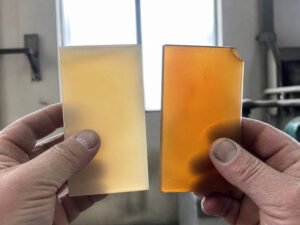
An immersion test is the evidence that matters for a containment floor. A cured sample is immersed in the actual chemical at the actual temperature for a defined period.
After immersion, the sample is checked for mass change, hardness change, blistering and adhesion loss. A result that passes all four is a result a plant can rely on.
Ask for the immersion test data for the three worst chemicals on site, at the temperatures they are stored, with the duration stated.
Where the chemical is a mixture, a proprietary cleaner or a process stream, ask for a test on the stream itself. A chart entry for one component tells you very little about a blend.
The cost of a test is a few hundred dollars. The cost of a failed bund is a containment incident with a regulatory report attached.
Splash zones and immersion zones are different floors
Most of a plant floor sees splashes, and a small area sees standing liquid: inside a bund, at a decanting point or under a valve.
A splash zone needs a coating that resists intermittent contact and cleans easily. An immersion zone needs a system tested for continuous contact.
Specifying the whole plant to the immersion standard is expensive and sometimes impossible, because the products differ in flexibility and build.
Chemical plant flooring specified across a whole process building at the immersion grade is often the wrong answer commercially, and it may not even be the right product in the dry areas. The screed versus coating call is per zone.
The practical approach is a zone drawing. Mark the immersion areas, mark the splash zone around them, and specify two builds with a clear boundary.
Where the boundary falls in a traffic route, put it at a joint rather than mid-slab, so the change of build coincides with a designed detail.
Photograph the finished zones and keep the drawing with the handover file. In five years, nobody will remember where the change was.
Joints, and why they decide the outcome
An expansion joint in a slab will move whether or not the liner covers it. A liner that bridges the joint rigidly will crack along the same line.
The correct detail carries the joint through the liner with a flexible insert, sealed to the membrane on both sides with a compatible system.
Construction joints that have stopped moving can be treated as static, but they still need a detail rather than a simple coat over the top.
Where an expansion joint crosses a bund wall, the detail has to accommodate movement in two planes. That is a designed component, not a bead of sealant.
Record every joint on the drawing with its type and treatment. A containment liner is only as continuous as its least considered detail.
Test the joints with a flood test in the completed bund, not with a visual inspection. Water finds what the eye does not.
Sumps, outlets and the way out
Every containment area needs a way to remove rainwater and wash water without letting the contents out. That is usually a sump with a valve or a pump.
A sump outlet is the highest-risk penetration in the whole liner, because it is a hole in the membrane at the lowest point.
Chemical plant flooring around a sump is also harder to place than on open floor, and the applicator needs access from both sides to dress the membrane into the flange.
The detail should use a flanged connection mechanically fixed and sealed to the liner, with the flange sitting on a resin upstand rather than on bare concrete.
Where a sump outlet is retrofitted into an existing bund, the seal is the weak point. Cut a chase, form a proper flange and test it before the area returns to service.
Valves should be accessible from outside the bund and should fail closed. A valve that needs someone to step into the containment area is a valve that will be left open.
Confirm the outlet capacity against the drainage plan, and confirm that the outlet is normally closed and opened only for controlled discharge.
Testing a containment floor
The tests should be written into the programme rather than agreed on site. A flood test that happens after the area is back in service proves nothing that a photograph would not.
Three tests matter: thickness, continuity and adhesion. Each answers a different question and none of them is optional on a containment area.
Thickness is proved by core samples at a stated frequency, with the location on a plan. A nominal 6 mm with a 10 per cent tolerance is a workable clause, and the sampling frequency rule belongs in the tender.
Continuity is proved by a flood test or, where the area is small, by a spark test on a conductive liner. A flood test at the design level is the most convincing evidence.
Adhesion is proved by pull-off tests, with the failure mode recorded. A high value with a clean interface failure is still a fail.
Table 1: Three tests and what each proves.
| Test | Proves | Frequency |
|---|---|---|
| Core sample | Thickness of the build | 1 per 500 square metres |
| Flood test | Continuity of the liner | Every bund |
| Pull-off | Bond to substrate | 1 per 500 square metres |

Figure 1: a bund holding water during the flood test, with the level marked on the wall.
Which details protect the liner in traffic?
A containment kerb does two jobs: it protects the liner edge and it tells a driver where the containment area begins.
The kerb is also the cheapest part of the containment system and the most frequently omitted, because it appears on the layout drawing rather than on the coating specification.
Height matters. A 150 mm kerb stops a pallet truck and does not stop a forklift, so the layout has to match the vehicles in the building.
Where a kerb is struck, the damage is local and repairable. Where a bund wall is struck, the repair is structural.
Paint or mark the kerb in a contrasting colour. In a busy plant the visual cue prevents more damage than the height does.
Provide a ramp or a dropped section at any point where a drum trolley has to cross, and detail it so the liner stays continuous through the transition.
Record the kerb line on the as-built drawing with its height and material, so that a later fit-out does not demolish it to widen a doorway.
The handover file for a containment area should also include the as-built drawing of the liner, the flood test record, the core locations and the immersion data for each chemical. That package is what a regulator will ask for after an incident, and assembling it afterwards is far harder than keeping it as the work proceeds.
Inspect kerbs after any reported impact. A cracked arris is the beginning of a path under the liner.
At vehicle routes, a containment kerb protects the wall from impact and keeps a pallet truck out of the bund. It also gives the liner a robust edge to terminate on.
Where a containment kerb is retrofitted, it should be cast or formed in resin rather than bedded on mortar, because mortar is porous and the bedding becomes a path.
Specifying a containment floor in eight lines
One: chemical plant flooring at 6 to 9 mm, with the immersion test evidence for the three worst chemicals on site.
Two: a secondary containment volume calculation, with the liner terminated above the calculated level on every wall.
Three: coves at all wall bases, and a containment kerb at every vehicle boundary.
Four: every expansion joint detailed with a flexible insert, sealed both sides, and recorded on the drawing.
Five: a sump outlet with a flanged, mechanically fixed connection on a resin upstand, valve accessible from outside.
Six: zone the splash zone separately from the immersion areas, with the boundary at a joint.
Seven: a flood test on every bund before handover, with the level and duration recorded.
Eight: a repair kit of the same material left on site, with the batch number, so a local chemical spill repair in year five matches the original.
Table 2: Containment details that are usually missing.
| Dettagli | Common omission | Conseguenza |
|---|---|---|
| Wall termination | Stops at floor level | Overflow path |
| Joint | Bridged rigidly | Crack along joint |
| Outlet | Sealant only | Leak at low point |
| Penetration | No collar | Path under liner |
| Kerbs | Missing at doors | Vehicle damage |
Table 3: Build by area in a process building.
| Area | Build | Exposure |
|---|---|---|
| Bund interior | 9 mm | Immersion |
| Decanting point | 9 mm, local | Frequent spill |
| Process floor | 6 mm | Splash |
| Traffic route | 6 mm, heavier seal | Abrasion |
| Control room | 3 mm | Dry |

Figure 2: the liner turning up the wall, with the termination above the marked level.
Frequently asked questions
Can a resin floor act as secondary containment?
Yes, if the liner, joints, kerbs and outlets are designed as one system and the bund is flood tested before handover.
What thickness is needed for a containment floor?
Six to nine mm of polyurethane screed, with nine mm in immersion areas and six elsewhere.
How is chemical resistance proved?
By an immersion test that soaks a cured sample in the chemical the plant actually handles, at its real temperature, then checks mass, hardness, blistering and adhesion.
Do expansion joints need special treatment?
Yes. A rigid fill over a moving joint cracks within a season; the detail has to move with the slab and stay sealed to the membrane.
How is a bund tested?
By filling it with water to the design level and holding it for a stated period, then inspecting every detail for seepage.
What is the difference between a splash zone and an immersion zone?
Splash zones see intermittent contact and can use a lighter build; immersion zones need a system tested for continuous contact.
Can a damaged liner be repaired?
Yes, locally, if the same material and batch are retained. Keep a repair kit on site with the batch number recorded.
Why food plants work with Kaida Paint
Kaida Paint supplies polyurethane screed flooring with immersion test data for named chemicals at stated temperatures, and we will detail the bunds, kerbs and outlets as one system rather than as separate products. Send the chemical list, the bund drawing and the largest vessel volume, and we will return the build, the details and the tests the containment area needs.
Autore: Mark Zhao, Senior Industrial Flooring Engineer Updated: October 2026


 English
 Spanish
 Portuguese
 Arabic
 French
 Italian
 Russian
 Indonesian
 Swedish