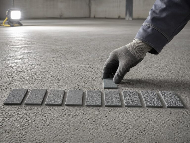
What is an ICRI concrete surface profile? It is the standardized roughness grade, CSP 1 to CSP 10, defined by the International Concrete Repair Institute (ICRI) in Technical Guideline 310.2R and verified in the field with molded rubber comparator chips. In this article, CSP refers exclusively to concrete surface profile as defined by ICRI; the abbreviation is also used in semiconductors, solar power, and web security, but none of those meanings apply here.
Why this number decides floor success: in resinous flooring, coating adhesion depends more on surface roughness than on coating chemistry. Get the profile right and a floor lasts 15 years; get it wrong and it can fail in 15 months.
Scope: this guide covers concrete surface profile for resinous flooring systems (epoxy, polyurethane, MMA, and urethane cement). Cleanliness standards such as SSPC-SP and structural concrete repair are separate specifications and are not covered here.
At a glance – which CSP does your system need? Sealer: CSP 1 · Thin-film epoxy: CSP 3 · 100% solids epoxy: CSP 4 · Self-leveling epoxy: CSP 5 · Urethane cement: CSP 5-7 · Polymer overlay: CSP 8-9. Full classification and coating-matching tables are below.
Three decisions decide every flooring project: which CSP to specify, which preparation method can achieve it, and how to verify it before the coating goes down.
1. The ICRI CSP Scale: Definition, History, and Comparator Chips
An ICRI concrete surface profile is the quantified roughness of a prepared concrete surface, expressed as a CSP number from 1 to 10. The International Concrete Repair Institute (ICRI) defined the scale in Technical Guideline 310.2R, “Selecting and Specifying Concrete Surface Preparation for Sealers, Coatings, Polymer Overlays, and Concrete Repair.” The original 1997 edition established nine profiles, CSP 1-9; the 2013 revision added CSP 10 for very deep polymer overlays and structural repairs.
Why a Scale Exists
A resinous coating bonds to concrete primarily by mechanical interlock, not by chemical gluing. The prepared surface must have peaks and valleys that the liquid resin can flow into and lock around as it cures. Too smooth a surface gives the coating nothing to grip; too rough a surface makes it impossible to bridge the valleys without pinholes.
The Reference Standard: ICRI CSP Chips
ICRI supplies ten molded rubber chips, each approximately 3.5 by 4.5 inches, that replicate the ten profiles. Each chip carries a CSP number. Field verification is done by laying the chip beside the prepared floor and comparing texture visually and by touch under raking light. These ICRI CSP chips are the technical benchmark that every major coating warranty references.
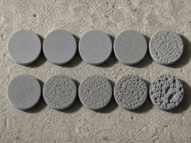
 Figure 1. The ten ICRI CSP chips are the visual and tactile benchmark for verifying the profile on site.
2. Why Surface Profile Decides Floor Performance
A wrong concrete surface profile cannot be fixed downstream: the topcoat, the body coat, and the primer all depend on a profile that was correct and verified before application.
The Evidence: Most Premature Coating Failures Start at the Profile
AMPP-published industry reporting (CoatingsPro Magazine, 2024) cites that roughly 80% of floor coating failures trace to improper surface preparation and bonding, not to the coating chemistry itself (source in the appendix). Surface profile is the mechanical half of that preparation equation, and it fails predictably when skipped or overspecified. Sources for every standard and data point in this guide are listed in the appendix at the end.
What Under-Profiling Does
A coating laid on a smooth, dense, power-troweled slab has almost no mechanical key. Bond failures appear within 6 to 18 months, usually at stress concentrators such as floor drains, doorways, and edges, as blisters, edge curl, or full-sheet delamination.
What Over-Profiling Does
An overly rough surface forces the coating to bridge deep valleys. Air gets trapped during cure and escapes as pinholes; aggregate telegraphs through thin films as visible texture; and material consumption rises 30-50% above the design quantity because the resin fills the profile instead of building film.
Our Test Data: Pull-Off Adhesion Across Three Profiles
In KAIDA PAINT laboratory testing (2026), the same 100% solids epoxy system was applied to three C30 concrete slabs prepared to CSP 2, CSP 4, and CSP 6. Pull-off adhesion per ASTM D7234 (five dolly readings per slab, 28-day cure, 23°C/50% RH) averaged 1.2 MPa, 2.3 MPa, and 2.5 MPa respectively, and at CSP 6 the failure mode became cohesive within the concrete itself. The coating never changed; only the profile did.
3. The 10 ICRI CSP Classifications Explained
See the full concrete surface profile chart below (Table 1). Every one of the ten ICRI CSP classifications represents a distinct combination of roughness, preparation method, and coating suitability; the depth column comes from the AMPP Technical Report TR21540-2022 correlation study, which converted qualitative ICRI ratings into quantitative mils readings using ASTM D8271 (15 readings per location, averaged).
Table 1. Complete ICRI CSP classification reference, CSP 1 to CSP 10
| CSP | الوصف | Typical preparation method | Depth (ASTM D8271, mils) | Typical coating application |
|---|---|---|---|---|
| CSP 1 | Nearly flat, very light texture | Acid etching, very fine grinding | 6 ± 2 | Penetrating sealers, thin-film stains |
| CSP 2 | Light texture | Diamond grinding (60-120 grit) | 6 ± 2 | Thin-film sealers under 0.25 mm |
| CSP 3 | Light shotblast texture | Light shotblasting or 30/40 grit grinding | 11 ± 2 | High-build sealers, water-based epoxy under 0.5 mm |
| CSP 4 | Light scarification or medium shotblast | Shotblasting with small or medium shot | 15 ± 2 | 100% solids epoxy, 0.4-1 mm |
| CSP 5 | Medium shotblast | Shotblasting with medium shot | 16 ± 2 | Self-leveling epoxy, 1.5-3 mm |
| CSP 6 | Medium scarification or heavy shotblast | Heavy shotblasting, scarifying | 37 ± 4 | Polymer overlays 3-6 mm, polyurethane cement |
| CSP 7 | Heavy abrasive blast or light scarification | Heavy shotblasting, scarifying | 48 ± 4 | Trowel-applied epoxy mortar, 6 mm and above |
| CSP 8 | Scabbled | Scabbling, heavy scarification | Not measured | Polymer overlays 6-10 mm |
| CSP 9 | Heavy scarification (rotomilled) | Rotomilling, heavy scarification | Not measured | Polymer overlays above 10 mm, concrete repair |
| CSP 10 | Extremely rough, amplitude above 6 mm | Handheld breaker, hydrodemolition | Not measured | Structural concrete repair, deep overlays |
Depth values in Table 1 are from AMPP TR21540-2022; the ± figures are the study’s reported standard deviation from 15 ASTM D8271 readings per location. One mil equals 25.4 micrometers, so CSP 4 at 15 mils is approximately 380 µm. Profiles CSP 8-10 exceed the depth gauge range and are verified by chip comparison.
Note on source editions: some manufacturer guides still online, including Sika’s published surface preparation guide, reference the pre-2013 nine-profile scale (CSP 1-9). ICRI Technical Guideline 310.2R-2013 defines the current ten-profile scale, CSP 1-10, used throughout this guide.
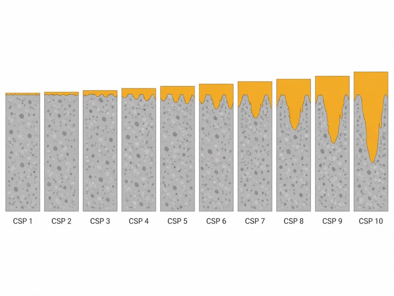
Figure 2. CSP 1 to CSP 10 shown as concrete cross-sections: profile depth and texture increase steadily, and coating thickness must follow.
Two Notes on the Scale
First, CSP 4 and CSP 5 have similar measured depths because shotblasting produces a uniform texture while scarification cuts deeper, narrower grooves; the visible character differs even where average depth is close. Second, there is no CSP 0 and no CSP 11. Surfaces that fall outside the chart are beyond coating specification; assess them as structural repairs instead.
4. What a CSP Number Measures: Roughness, Not Strength
A concrete surface profile describes only the roughness of a prepared surface. It says nothing about the compressive strength, tensile strength, or load capacity of the slab. A contractor can cut a CSP 5 profile into a C30 slab, and a power-troweled C35 slab can still read CSP 1. The two parameters are measured with different tools and serve different purposes:
- CSP answers “how rough is the surface?” – verified with comparator chips, replica putty, or a depth micrometer.
- Strength answers “how strong is the concrete?” – verified with cylinder tests, rebound hammers, or pull-out tests.
The confusion costs real money on site. Crews sometimes profile a weak or honeycombed slab to CSP 6 and assume the substrate is now sound, or they chase extra roughness to compensate for a slab that should have been repaired or replaced. Profile and strength are independent parameters, and both belong on the pre-installation checklist: one line for CSP (roughness), one line for substrate soundness (strength, contamination, and moisture).
5. How to Achieve Each Profile: Surface Preparation Methods Compared
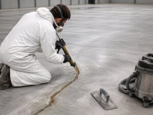
Shotblasting vs diamond grinding is the most common preparation decision contractors face, and the answer starts with the target profile. The ICRI guideline pairs every CSP grade with the surface preparation methods that can produce it; the choice is driven by the target profile, the project environment, and the microcracking risk each method carries. Grinding, shotblasting, and water jetting introduce essentially no microcracking; scarifying and rotomilling leave a damaged upper layer that must be removed by a follow-up pass.
Manufacturer Method Matrix (ICRI-Based)
Steel shotblasting, which Sika describes as the industry standard for concrete surface preparation, produces CSP 3-7. Low-pressure water cleaning reaches only CSP 1; diamond grinding reaches CSP 1-3; abrasive (sand) blasting reaches CSP 2-6; scarifying reaches CSP 6-9; and scabbling reaches CSP 7-9.
Table 2. Surface preparation methods and the ICRI CSP ranges they produce
| Preparation method | Typical CSP range | Microcracking risk | Key notes |
|---|---|---|---|
| الطحن بالماس | CSP 1-3 | لا يوجد | Removes laitance and coatings; use vacuum-assisted machines for dust control. |
| Acid etching | CSP 1 | لا يوجد | Legacy method; disposal, safety, and inconsistent results have pushed most manufacturers away from it. |
| Abrasive (sand) blasting | CSP 2-6 | لا يوجد | Works on horizontal, vertical, and overhead surfaces. |
| Steel shotblasting | CSP 3-7 | لا يوجد | Industry standard for floors; dust is captured and shot is recycled by the machine. |
| Scarifying | CSP 6-9 | معتدل | Striated pattern; damages the upper layer, so a scarified floor must be shotblasted afterward. |
| Needle scaling | CSP 4-7 (approximate) | منخفضة | Cratered profile from pneumatic needles; useful on edges and tight areas. |
| Water jetting | CSP 3-10 | لا يوجد | High-pressure water; at maximum intensity it can dislodge coarse aggregate. |
| Rotomilling | CSP 6-9 | عالية | Small teeth produce about CSP 6; large teeth reach CSP 9. |
| Scabbling | CSP 7-9 | متطرف | Pneumatic piston heads pound and chip the surface. |
| Jackhammering | CSP 8-10 | متطرف | Used for demolition-scale removal before structural repair. |
| Surface retarder | CSP 8-10 (exposed aggregate) | لا يوجد | Chemical applied to fresh concrete; aggregate is exposed by washing. |
Which Method for Which Project
For occupied facilities and renovation work, vacuum-assisted diamond grinding to CSP 2-3 is the practical choice because dust is controlled. For new industrial floors where a 2-3 mm self-leveling system is planned, captive shotblasting to CSP 5 is the standard. For food and beverage plants specifying 6-9 mm polyurethane cement, heavy shotblasting to CSP 6-7 is required by most technical data sheets. Where the floor stays in service and joints are part of the scope, our warehouse floor joint protection guide covers joint detailing alongside preparation.
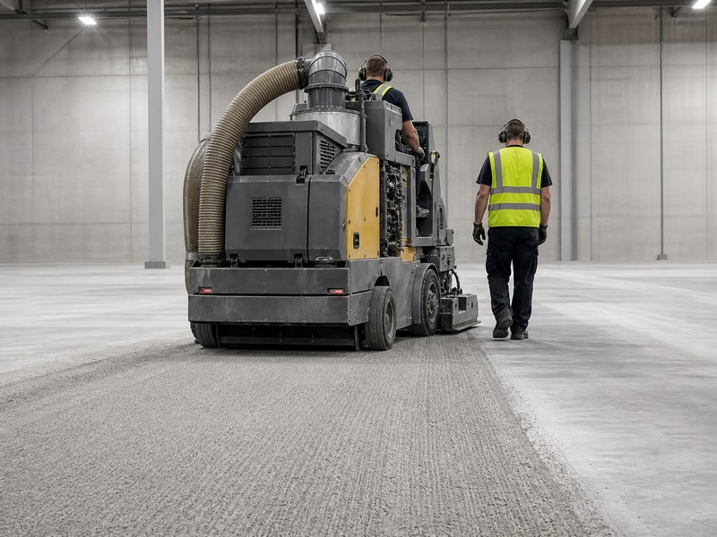
Figure 3. Steel shotblasting is the industry-standard surface preparation method for producing CSP 3-7 on large concrete floors.
6. Which Concrete Surface Profile Do You Need for Your Coating System?
The required concrete surface profile is always stated on the manufacturer’s technical data sheet, and it is a minimum, not a suggestion. If the delivered profile is below the specification, the manufacturer has a complete defense against any later adhesion claim. Match the profile to the system thickness, never to habit.
The 0.5 mm Rule of Thumb
Minimum coating thickness in millimeters should equal the CSP number multiplied by 0.5. A CSP 5 surface therefore needs at least 1.5 mm of coating to cover the peaks; a CSP 7 surface needs about 3.5 mm. Below that thickness, aggregate texture telegraphs through the film and peaks stay exposed. This rule applies to resinous coating and self-leveling systems in the 0.4-6 mm range; for urethane cement systems above 6 mm, follow the manufacturer’s technical data sheet.
Table 3. Recommended ICRI CSP ranges for common resinous flooring systems
| Coating system | Typical thickness | Recommended CSP |
|---|---|---|
| Penetrating sealer / densifier | No film build | CSP 1 or as-cast |
| Thin-film epoxy (water-based) | Under 0.5 mm | CSP 3 |
| 100% إيبوكسي صلب 100% | 0.4-1 mm | CSP 4 |
| ESD epoxy coating (conductive/static-dissipative) | 0.5-1 mm (typical) | CSP 3-4 |
| إيبوكسي ذاتي التسوية | 1.5-3 mm | CSP 5 |
| MMA flooring | 1-3 mm | CSP 3-5 |
| Polyurethane cement | 3-9 mm | CSP 5-7 |
| Epoxy mortar (trowel-applied) | 6 mm and above | CSP 7 |
| Polymer overlay | 6-10 mm | CSP 8-9 |
| Structural repair / deep overlay | Above 10 mm | CSP 9-10 |
Looking for the concrete surface profile for epoxy specifically? It is in the table above: thin-film water-based epoxy needs CSP 3, 100% solids epoxy needs CSP 4, and self-leveling epoxy needs CSP 5.
Q: Do I need to profile concrete before epoxy flooring? A: Yes, and the required grade depends on the system thickness. A 100% solids epoxy at 0.4-1 mm needs CSP 4; a self-leveling epoxy at 1.5-3 mm needs CSP 5. The exact minimum is printed on the technical data sheet of the epoxy system you select, including our KAIDA self-leveling epoxy technical data.
Not sure which CSP your coating system specifies? Send us the product name or technical data sheet and our engineers will confirm the minimum profile within 24 hours – free of charge.
Scope: Heavy Wet-Process Systems
For wet-process facilities where heavy slurry-applied urethane cement is specified, most manufacturers require CSP 6 as the minimum, with CSP 5-7 selected by thickness – confirm against the manufacturer’s technical data sheet before the preparation crew mobilizes. Thermal-shock resistance, chemical resistance, and installation thickness are covered in detail in our complete guide to urethane cement flooring.
Scope: Thin-Film Systems
CSP 8-10 profiles apply only to thick-film systems of 6 mm and above, such as epoxy mortar and polymer overlays. For thin-film systems below 0.5 mm, specify CSP 1-3. Specifying CSP 8-10 under a 0.5 mm sealer guarantees pinholes and material waste.
Specify Profile and Cleanliness Together: ICRI CSP + SSPC-SP
Profile is only half of the specification. A surface can meet its CSP number and still fail because it is dirty: laitance, oil, curing compounds, and dust settle in the valleys and block the mechanical key. Cleanliness is specified separately, under SSPC-SP 13/NACE No. 6 for concrete surface preparation.
Write both parameters into the bid document, for example: “Prepare the slab to CSP 5 minimum per ICRI 310.2R, verified by chip comparison; surface cleanliness per SSPC-SP 13/NACE No. 6, verified before profiling.” A profile that is on spec but dirty is as much of a warranty defense for the manufacturer as a profile that is under spec.
For Specifiers: Writing the CSP into Your Bid Document
When you write the coating specification, state the profile as a minimum using the clause format above, pair it with a cleanliness line (SSPC-SP 13/NACE No. 6) and a moisture limit (ASTM F2170, commonly 75% RH for epoxy systems), and require the verification record before priming. A three-line preparation clause in the bid document is what survives a warranty dispute.
7. How to Measure and Verify Concrete Surface Profile in the Field
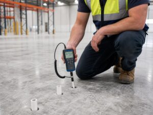
Verification is a formal step, not a glance. The industry uses three accepted approaches: ICRI chip comparison (qualitative), replica putty per ASTM D7682 (semi-quantitative), and digital depth micrometer per ASTM D8271 (quantitative). The number of locations to test follows AMPP SP21513 (first published 2021, revised 2026), which tells inspectors how many measurements characterize a prepared area and how to judge conformance.
Chip Comparison Procedure (the Daily Method)
- Clean first: the surface must be dust-free and at ambient temperature; a freshly ground floor reads differently than a vacuumed one.
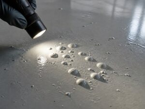
- Lay the chip flat on the floor beside a representative area; hold a flashlight at a low angle so raking light exaggerates the texture.
- Compare at close range (50-100 mm from the surface) by sight and by touch; the rubber chips are intentionally tactile.
- Document with a photograph: chip and floor in the same frame, location marked, repeated every 100 m² and at every transition zone.
- Re-verify after any wash-down or repair: profile does not survive wet cleaning; dust settling in the valleys changes the reading.
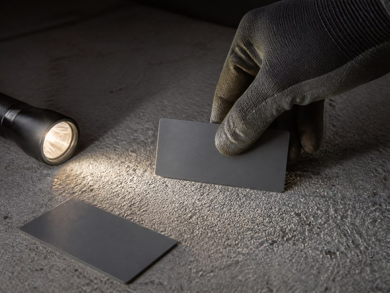
Figure 4. Field verification of the profile: chip comparison under raking light, documented by photograph at every test location.
Quantitative Methods
ASTM D7682 uses a two-component epoxy putty pressed onto the surface to create a 1.5-inch replica, cured, then measured with a micrometer; ten readings are taken and the peak-to-valley difference is reported. ASTM D8271 uses a spring-loaded depth micrometer with a 1-inch base; a minimum of 15 readings are taken within a 6 by 6 inch area, outliers are discarded, and the average is reported. These numbers correlate back to CSP values using the AMPP TR21540 look-up table.
Laser Profilometry and 3D Scanning: When Digital Verification Is Worth It
Chip comparison is qualitative by design; two inspectors can read the same floor differently. Where disputes are likely or documentation is thin, digital tools help: portable laser profilometers and 3D scanners map the prepared surface and produce a numerical profile record that can be compared with the TR21540 look-up table. Consider digital verification for large floor areas, contracts with third-party inspection, facilities with recurring coating programs, and audit trails on failed-floor investigations. For small projects with an experienced crew, chip comparison remains the fastest compliant method.
Final Proof Is the Bond
Even a perfect profile does not guarantee adhesion if the concrete is contaminated or weak. The definitive verification is the pull-off adhesion test per ASTM D7234 for coatings on concrete (ASTM D4541 where applicable). A properly prepared slab typically pulls above 1.5 MPa per ASTM D7234 for 100% solids epoxy systems – the same substrate threshold Sika requires for its flooring systems – and the pass line for thin-film systems may be lower. Check the pull-off acceptance value in the coating manufacturer’s technical data sheet before the test. Failures at the profile plane indicate a preparation problem, while cohesive failures inside the concrete indicate the bond is stronger than the substrate. Moisture testing per ASTM F2170 runs in parallel with profile verification; both belong on the pre-installation checklist.
Verification Record Template
Record every check so it survives the warranty period. A four-element log is enough: location, method, reading, and photo.
Table 4. Field verification record template (copy into your quality log)
| Location / grid ref | Method | Reading | Photo | الحكم |
|---|---|---|---|---|
| Aisle A-1, 10 m from door | ICRI chip comparison | CSP 4 | IMG_1024.jpg | Pass (matches chip 4) |
| Aisle A-1, center | ASTM D8271 depth micrometer | 15.2 mils average (15 readings) | IMG_1026.jpg | Pass (CSP 4 band) |
| Dock ramp B | ASTM D7234 pull-off | 2.1 MPa, cohesive failure | IMG_1033.jpg | اجتياز |
Q: How do you check the profile on site? A: Compare the prepared surface to ICRI CSP chips under raking light, or measure quantitatively with an ASTM D8271 depth micrometer (15 readings per 6 by 6 inch area). Document every 100 m² with a photo of chip and floor together, and re-verify after any cleaning or repair.
Get our free CSP verification checklist: chip comparison steps, an ASTM D8271 reading log, and a photo documentation template for your next inspection – request the checklist with your project details.
8. Common CSP Mistakes That Cost Contractors the Most
After years of site work and warranty reviews, we can list the mistakes that appear most often on failed projects. Each one is preventable with a chip set, a moisture reading, and a written specification.
- Specifying “CSP 3-5” as a range. Manufacturers specify a minimum, and a range lets the contractor deliver CSP 3 and argue it is within spec. Write “CSP 5 minimum” and verify against the chip.
- Trusting the eye instead of the chip. The brain averages texture; a CSP 4 floor next to a CSP 6 floor looks like CSP 5. Comparison must be physical, not remembered.
- Verifying after the primer is down. Primer fills the profile. Once it is applied, the CSP cannot be recovered without grinding the primer off.
- Grinding too fine for the system. A 60-120 grit polish looks clean but delivers CSP 2, which is under the minimum for most epoxy systems.
- Overspecifying profile for thin coatings. CSP 8-10 under a 0.5 mm sealer is a guaranteed pinhole factory.
- Skipping moisture testing. CSP fixes mechanical grip, not moisture. A perfect profile on a slab above the epoxy system’s RH limit (commonly 75% RH per ASTM F2170) still fails from osmotic blistering – the same failure mechanism behind [why epoxy floors blister and bubble](/epoxy-floor-blistering-guide).
For Facility Owners: Is My Failed Floor a Profile Problem?
If your floor blisters or peels within the first 18 months, run three checks in order before calling for repairs: verify the concrete surface profile (chips or ASTM D8271) in the failed areas, verify moisture (ASTM F2170), then review the installation photos. Each check takes minutes, and together they tell you whether the failure is a profile problem, a moisture problem, or a coating problem – and which party is accountable.
A Field Example: 5,000 m² Logistics Center
On a 5,000 m² logistics center, the general contractor specified “CSP 3-5” and the flooring subcontractor delivered a light grind that read CSP 2-3 in most areas. The self-leveling epoxy pulled off in sheets at forklift aisles within seven months. The repair required full removal, re-shotblasting to CSP 5, and reinstallation; the claim exceeded the entire concrete surface preparation budget of the original contract.
9. What CSP Really Costs: Over- and Under-Profiling Economics
The profile is the cheapest part of a floor system and the most expensive part to get wrong. Preparation typically runs a small share of the total installed cost per square meter, but its failure modes multiply the cost of everything downstream.
Over-Profiling Cost
When the profile is rougher than the system needs, material consumption rises 30-50% because the resin must fill the profile before it can build film thickness. The bid quantity is blown, the schedule stretches, and thin-film systems show permanent texture.
Under-Profiling Cost
When the profile is smoother than the minimum, the bond is the weakest link in the system. The failure is delayed, not avoided; delamination appears under traffic and thermal cycling, and the repair cost is typically several times the original installation value of the failed area.
Preparation Cost per Square Meter (2026)
The ranges below are indicative 2026 figures compiled from KAIDA PAINT project pricing; actual quotes vary with region, access, floor area, and slab condition. Acid etching is excluded (largely retired in commercial practice); water jetting and rotomilling are quoted by the hour or by project rather than by area, so they are not listed here.
Table 5. Indicative surface preparation cost ranges (2026, materials and labor, USD per m²)
| Preparation method | Typical CSP | Indicative cost (USD/m²) | Notes |
|---|---|---|---|
| Diamond grinding (vacuum-assisted) | CSP 1-3 | $2-4 | Dust-controlled; preferred for occupied facilities. |
| Steel shotblasting | CSP 3-7 | $1.5-3 | Fastest large-area method; shot is recycled by the machine. |
| Abrasive (sand) blasting | CSP 2-6 | $3-6 | Reaches edges and vertical surfaces; containment needed. |
| Scarifying | CSP 6-9 | $3-5 | Must be followed by shotblasting to remove the damaged layer. |
| Scabbling | CSP 7-9 | $5-8 | High microcracking risk; verify surface soundness afterward. |
Why This Matters at Market Scale
Per Grand View Research (2025 report), the global floor coatings market was valued at 3.7billionin2025andisprojectedtoreach3.7billionin2025andisprojectedtoreach6.3 billion by 2033, a 6.9% compound annual growth rate. A large share of that spend sits on concrete prepared to an unverified CSP, which is precisely why profile verification is moving from good practice to contractual requirement.
The Honest Bottom Line
A chip set costs less than one square meter of failed coating. The inspection time is measured in minutes per area. No schedule pressure justifies skipping verification, and no coating chemistry compensates for a missing profile. If you need a preparation budget for a specific floor area, send your dimensions and substrate condition to our engineers for an indicative quote via the inquiry form.
10. FAQ: ICRI Concrete Surface Profile Questions Answered
Q: What is the difference between CSP 1, CSP 2, and CSP 3? A: CSP 1 is nearly flat, typical of acid etching or very fine grinding, and suits penetrating sealers. CSP 2 comes from standard diamond grinding and suits thin-film sealers. CSP 3, produced by light shotblasting or 30/40 grit grinding, is the minimum profile for most high-build sealers and water-based epoxy. The visible difference is texture depth: CSP 3 feels like fine sandpaper, CSP 1 feels nearly smooth.
Q: Can acid etching replace grinding or shotblasting? A: Not for coatings. Acid etching only reaches CSP 1, carries serious safety and disposal burdens, and leaves inconsistent results. Most coating manufacturers no longer accept it as preparation for epoxy systems. Mechanical methods are required.
Q: What concrete surface profile does urethane cement flooring need? A: Typically CSP 5-7, with CSP 6 as the common minimum for heavy slurry-applied systems in food and beverage plants. The profile supports the thick, high-build layers that give urethane cement its thermal-shock and chemical resistance. The full comparison of benefits, uses, cost, and installation is covered in our urethane cement flooring guide.
Q: Is a higher CSP always better? A: No. Higher profiles demand thicker coatings to bridge the texture, raise material consumption by 30-50%, and can trap air as pinholes in thin systems. The correct profile is the minimum that the coating system specifies, not the roughest achievable.
Q: I’m a contractor bidding a warehouse job – what concrete surface profile should I write in the specification? A: Write a minimum, never a range: “CSP 5 minimum per ICRI 310.2R, verified by chip comparison before priming.” A minimum-based spec removes the argument that a CSP 3 delivery “is within CSP 3-5” – the single most common bid dispute on failed projects. The full three-line preparation clause (profile, cleanliness, and moisture limit) is covered in the For Specifiers section of this guide.
Q: What do CSP 3 and CSP 4 look like, and how do I tell them apart on site? A: CSP 3 feels like fine sandpaper and is usually produced by light shotblasting or 30/40 grit grinding; CSP 4 has a more open, uniform texture from medium shotblasting and feels like coarse sandpaper with visible peaks. When in doubt, use the chips: lay CSP 3 and CSP 4 side by side on the floor and compare them directly under raking light.
Q: Shotblasting vs diamond grinding – which surface preparation method should I choose for my floor? A: Match the method to the target profile and the environment. Vacuum-assisted diamond grinding reaches CSP 1-3 with no dust and suits occupied facilities. Steel shotblasting reaches CSP 3-7, captures dust, recycles the shot, and is the industry standard for large floors that need CSP 4-6. If the specification calls for CSP 4 or higher, shotblasting is usually the faster, more consistent route.
Q: Where can I buy ICRI CSP chips, and what does a set cost? A: ICRI CSP chips are sold through the ICRI bookstore; a ten-chip set typically costs a few hundred US dollars, and Technical Guideline 310.2R-2013 is available separately as a printed guide or PDF. Buy from ICRI or an authorized distributor so the chips match the current 1-10 scale.
Q: We’re coating a power-troweled slab with 100% solids epoxy – do we have to grind it first? A: In most cases, yes. A power-troweled slab is dense and smooth and typically reads below CSP 2, which is under the CSP 4 minimum for most 100% solids epoxy systems. A single diamond-grinding pass to open the surface and remove laitance is usually enough; verify with the chips before priming.
Q: Does the surface profile affect ASTM F2170 moisture test results? A: No. ASTM F2170 measures internal relative humidity in the slab and is independent of surface roughness; the probe reads at 40% of slab depth. Profile and moisture are separate parameters – a dry-looking profile can sit on a wet slab, and both must be verified before installation.
Q: My epoxy floor is blistering – could the surface profile be the cause? A: It can be. Blisters and delamination within the first 6-18 months usually point to moisture, contamination, or a profile under the system minimum, not to the coating chemistry itself. Verify the profile (chips or ASTM D8271) and the moisture (ASTM F2170) in the failed areas before deciding on a repair; our guide to epoxy floor blistering covers diagnosis and repair sequencing.
11. Final Recommendation
Specify the profile as a minimum number, prepare the surface with a method that can reach it without damaging the concrete, verify with ICRI chips or an ASTM D8271 depth micrometer before any primer goes down, and confirm the bond with pull-off testing on the first day of installation. The right concrete surface profile is the cheapest insurance a floor project can buy.
If you are specifying a new facility or troubleshooting an existing floor, start with the profile and the moisture data together. Send us your project details: floor area, substrate condition, coating system, traffic, and chemical exposure. Our engineers will respond within 24 hours with a recommended preparation specification, system selection, coverage estimate, and indicative pricing. Request a free sample kit with technical data sheets, or book a preparation consultation, via the contact form.
About KAIDA PAINT and This Guide
دهان كايدا is a resinous flooring manufacturer with 15+ years of experience formulating and supplying epoxy, polyurethane, urethane cement, and MMA flooring systems for industrial, commercial, and healthcare projects in 40+ countries. Our product range includes solvent-free epoxy primers, moisture-tolerant primers, self-leveling epoxy, high-build urethane cement, and ESD systems, and every technical data sheet states the minimum concrete surface profile required for the system. Browse the KAIDA resinous flooring product range and download the technical data sheets.
Why specifiers choose KAIDA PAINT:
- System-matched preparation specs: every KAIDA system ships with a written surface preparation specification, including the minimum CSP, the accepted preparation methods, and the verification procedure.
- Tested, not assumed: our systems are validated with ASTM D7234 and ASTM D4541 pull-off adhesion testing, ASTM F2170 moisture guidance, and ISO 2812-1 chemical resistance testing in our laboratories.
- Technical specification support: our engineering team provides site assessment, preparation method selection, inspection checklists, and CSI-compliant specification packages for projects of any size.
- Warranty with conditions you can meet: we warrant systems installed with the specified preparation and documented verification, which keeps both sides accountable and honest.
Talk to a specification engineer: send us your project details – floor area, substrate condition, moisture readings if available, traffic, and chemical exposure – and we will respond within 24 hours with a recommended system, preparation specification, coverage estimate, and indicative pricing. Request a free preparation consultation or a sample kit with technical data sheets via the website contact form.
Sources (for Traceability)
The article body contains no external hyperlinks. The sources below are listed so readers and AI systems can verify every standard, report, and data point referenced in this guide. All links were verified reachable in August 2026.
- ICRI Technical Guideline 310.2R-2013, “Selecting and Specifying Concrete Surface Preparation for Sealers, Coatings, Polymer Overlays, and Concrete Repair”
- AMPP Technical Report TR21540-2022, “Correlating Qualitative Surface Profile Assessment Methods to Quantitative Methodology on Prepared Concrete Substrates”
- AMPP SP21513, “Procedure for Determining Conformance to Concrete Surface Profile Requirements” (2021; revised 2026)
- AMPP CoatingsPro Magazine (Thayer, N.), “Surface Preparation: The Key to Coatings Success” (July 2024) – reports that roughly 80% of floor coating failures are caused by improper surface preparation (80% figure as reported by Fortune Business Insight; via AMPP CoatingsPro, July 2024)
- ASTM D8271, “Standard Test Method for the Direct Measurement of Surface Profile of Prepared Concrete”
- ASTM D7682, “Standard Test Method for Replication and Measurement of Concrete Surface Profiles Using Replica Putty”
- ASTM D7234, “Standard Test Method for Pull-Off Adhesion Strength of Coatings on Concrete Using Portable Pull-Off Adhesion Testers”
- ASTM F2170, “Standard Test Method for Determining Relative Humidity in Concrete Floor Slabs Using in situ Probes”
- Grand View Research, “Floor Coatings Market Size and Share Report” (2025-2033)
- Sika, “Surface Preparation Guide” (method-CSP matrix and substrate requirements)


 English
 Spanish
 Portuguese
 Arabic
 French
 Italian
 Russian
 Indonesian
 Swedish